|
Dismantling the locomotive |
|
|
Unplug the plastic plug connecting the cables from the locomotive to the tender. This cabling will be used in future so be careful not to deform it. Unscrew the bolt on the locomotive which holds the locomotive to the tender drawbar. This is a special bolt with a waist so be extra careful not to lose it. Unscrew the front and two middle Philips screws in the plastic keeper plate. Pull the chassis block down from the front (there is a tab at the rear which holds it in place). The keeper plate should come away from the main chassis block. While the wheels and coupling rods are not required, the final drive gear is needed. Remove the wire which represents the sanding gear. Hold the rear axle in a pair of pliers and remove the wheels with a twisting motion, slide off the brass bushes (they can be very tight). Place the axle with the centre gear in a vice so that the gear wheel is supported on the vice sides but the axle is loose, tap the axle with a small hammer or similar and the gear wheel will slide off the axle. If you do not have a vice use a pair of pliers on one side of the gear wheel, gently slide the plastic gear down and off the axle by holding the axle vertical and pressing down. It is very important not to damage this gear. You will now have a box of bits and an invalid Hornby guarantee! |
|
|
Modifications to the Hornby chassis block |
|
|
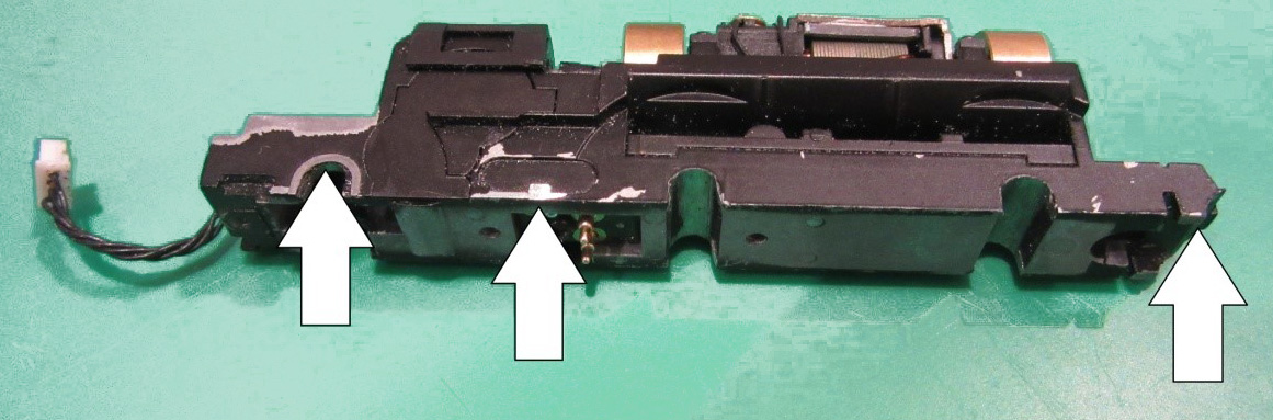
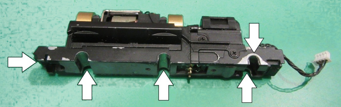
A little filing is now required. The metal used for the chassis block is relatively easy to file but take care to avoid getting the filings into the motor or gears. It is a good idea to wrap some Sellotape around the motor to avoid this. Unless you are using the Alan Gibson conversion set with 2mm diameter axles each of the wheel bearing slots needs widening slightly to ensure that your chosen axle size will move freely. There is a slight ridge inside each of the bearing slots which retained the original brass bearing, This will need to be removed to allow an 1/8" axle bearing to slide freely. There is also a little extra material to remove from the sides of the block around the rear axle slot. Remove the guard irons. This is a job for a razor or piecing saw. File the cut smooth. Finally, on the right-hand side of the block there is a little rectangular block ~1mm x 1.5mm which needs to be removed so that the new side frames can be easily slid on. The photographs make clear what to remove. |
|
| Preparing the wheels | |
|
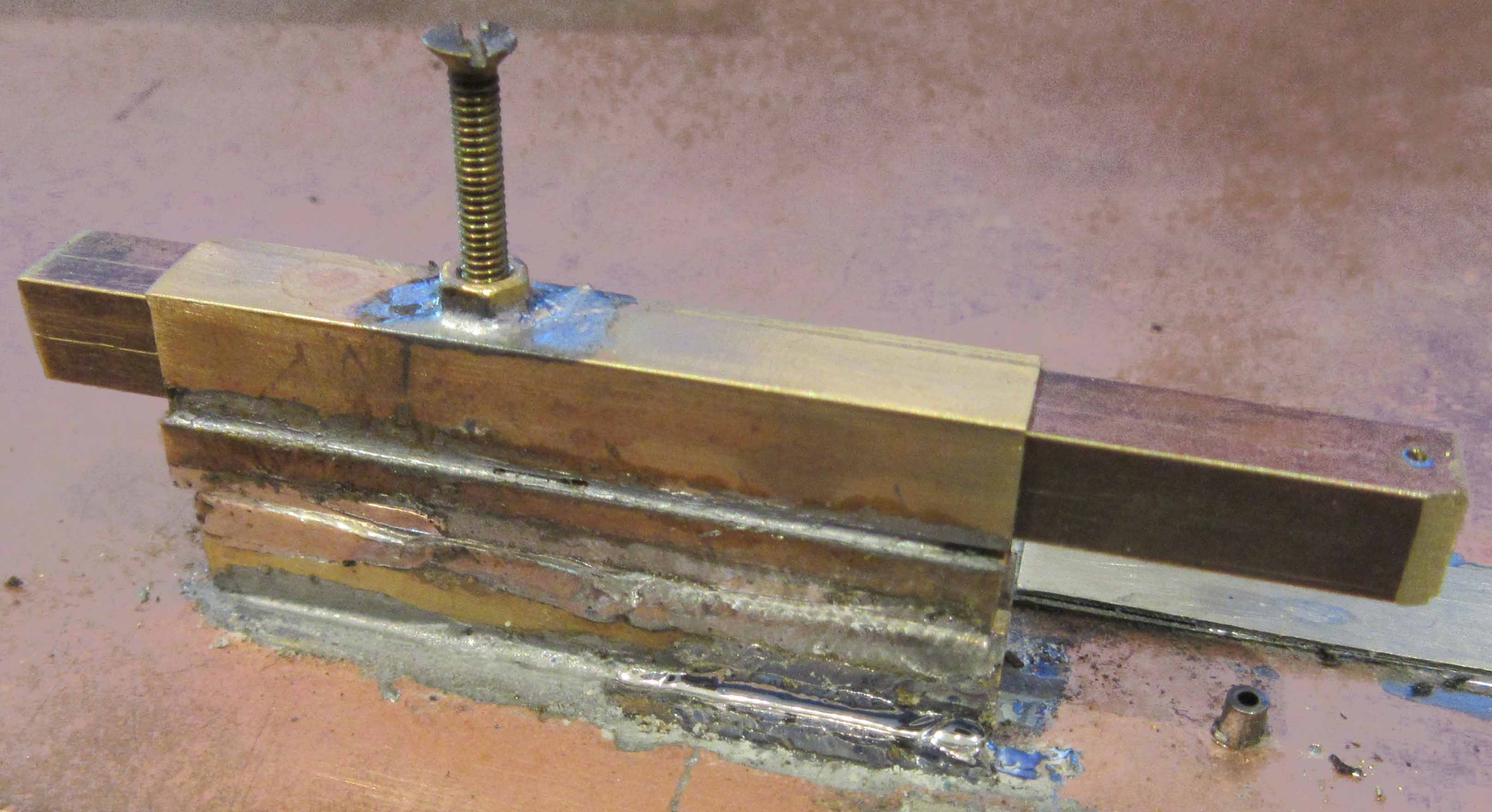
If you are using Alan Gibson wheels you may need to drill the crankpin holes using a 0.65mm drill. The hole must be perpendicular to the wheel. It is worth making a little jig to ensure that all the holes are drilled perpendicular and the same distance from the wheel centre. This is useful for all wheels where the crankpin holes need to be drilling and is re-usable on future projects not just EasiChas. The Gibson wheels have quite a large boss on the rear which fouls the head of the crank pin bolt. Ensure that you cut away a section of this boss around the crankpin hole otherwise the countersink of the crankpin will tend to twist it 'off true' when it hits the boss. The following will prevent problems with loose crankpins. Countersink the rear of the crankpin screw holes using a 3mm drill and half screw the 12BA screws home. Using 24-hour epoxy adhesive, smear the remaining thread and screw the 12BA screws home. Smear a little epoxy over the head for additional security but there should not be a big blob that will catch on wheel rotation. Leave in a warm place for 24 hours to set. This will retain the screws and stop them from rotating. |
 |