|
Basic locomotive conversion |
|
|
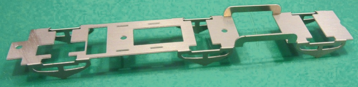
Remove the main frame [L1] from the etch. Clean up the residual tabs with a small file. Fold up the main frames using bending bars or a pair of steel rules to produce a U-shape. All the half-etches are on the inside of the bend. Strengthen the bend with a bead of solder. Bend the front bolt bracket, This bends back on itself and has tabs which form sides that fit into the slots on the top side. It is easiest to start with bending the two sides and then roll the part back into the slots in the main cross member of the chassis. These tabs need soldering into the frames for strength. It is deliberately a tight fit in the Hornby chassis to prevent unwanted movement and may need some filing on the sides to fit. Fold inwards by 90 degrees, the tops of the frames which provide spacers between the new frames and the Hornby chassis block. Fold down the little hooks next to the front bolt bracket. These secure the keeper plate with the cosmetic locomotive springs which forms the lower part of the chassis. Also fold down the brake rod support at the rear. Strengthen with a bead of solder. Enlarge the holes for the mounting screws slightly with a broach until the Hornby screws are a comfortable fit. It is ideal (though not vital) to keep the rear hole slightly tight so that the Hornby screw with the waist for the coupling bar holds slightly on its thread as this will mean you can use it to hold the main frame and the keeper plate together while rolling the chassis without the chassis block in place. The finished frames should look like this. |
 |
|
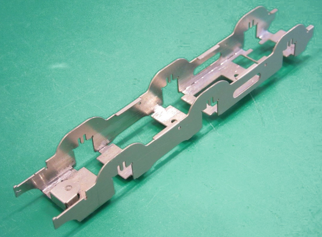
Check the fit of the brass bearings into the slots in the mainframes. If tight, using a smooth sharp file lightly file away the cusp equally on both of the edges of the slots until the bearing slides up and down with no binding. It is very important that too much metal is not removed resulting in a sloppy fit – no side play whatsoever is the aim, just a smooth sliding fit. Remove the chassis keeper plate [L2] from the etch. Clean up the residual tabs with a small file. Fold down the cosmetic springs and strengthen the bend with a bead of solder. Fold up the section of frame at the front which slots between the mainframes and strengthen the bend with a bead of solder. Enlarge the mounting holes with a broach until the Hornby bolts are a comfortable fit. Test fit the keeper plate into the bottom of the main frames, It should clip under the retaining hooks in the front of the frame. The waisted bolt which connected the locomotive to the tender drawbar can be used to hold these together. IMPORTANT - Carefully examine the bearings as they are not symmetrical. It can be seen that the flange on one side of the slot is wider than the other side. For EM gauge, the bearings need to be mounted in the frames with the thicker flange towards the centre of the frames. For P4 gauge, the bearings need to be mounted with the thinner flange towards the centre of the frames. Increased side-play on the middle wheels can be obtained by having the thin side of the bearings on the outside or rubbing off the circular beading round the axle hole. For EM gauge, it will be necessary to file off the raised rim on the inside face of the bearings to ensure the bearings move up and down freely. If using Gibson's conversion wheel set with 2mm axles fit the reducing sleeves into the hornblocks, file flush with the surface of the hornblocks and ideally ream the resulting bearing with a 2mm reamer. |

|
|
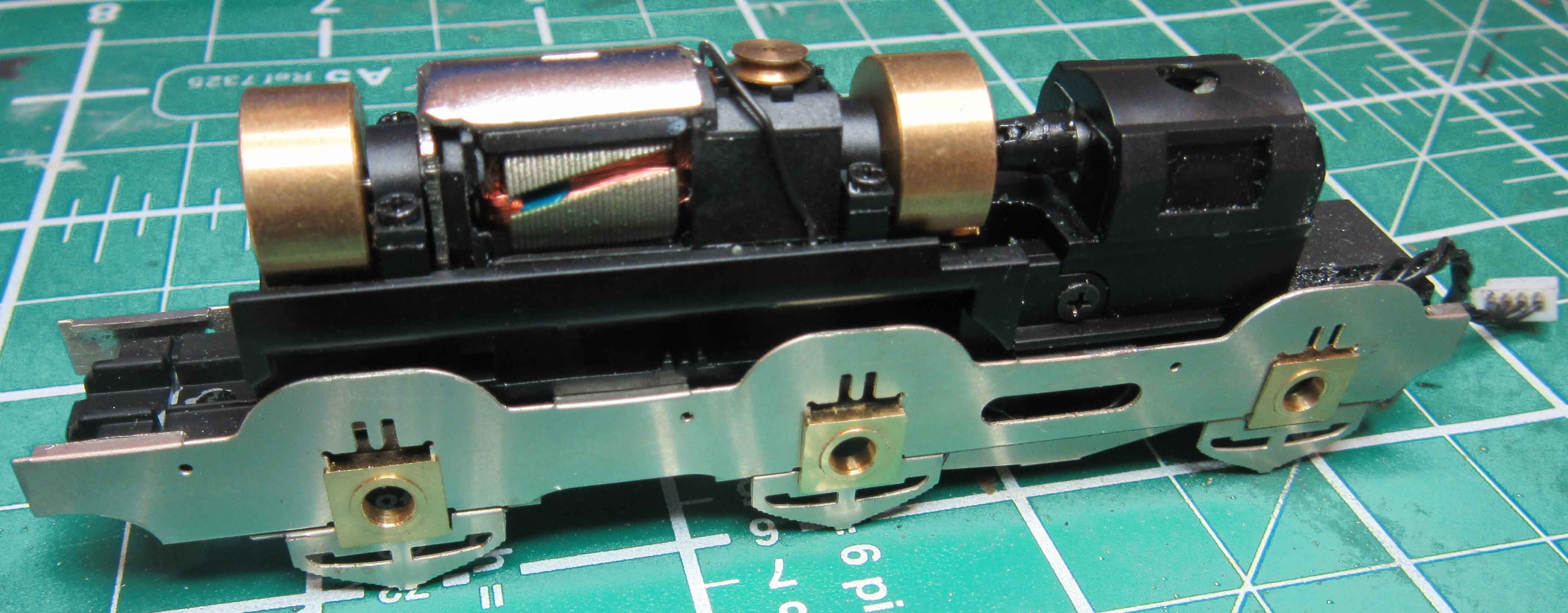
Fit the mainframes to the Hornby chassis,
place the bearings in the slots and check for easy movement. If using the Alan Gibson 2mm axles you will need to 'knurl' the drive axle so that the gear wheel has something to grip on to. Place the plain axle into the chassis, measuring on the axle the overhang each side to make sure it is central. Take a permanent marker pen and mark the position of the gear on the axle. Place the axle on a cutting mat or similar. Take a small hand file, we use a 4 inch second-cut file, and using the file on edge, roll it with firm downward pressure over the axle where you marked the gear position. Do not stray away from this narrow area, as we do not want knurling where the axles run in the areas of the hornblocks. If you are using Alan Gibson wheels you may find the axles are slightly over length for P4. They need to be approximately 22.6 mm long. You will also need to re-use the Hornby axle gear wheel. If you are using 1/8" axles then the axle hole in the Hornby gear wheel will need to be made larger. This is best done using an increasing range of broaches and/or drill bits. Take it easily and gently in small steps. The gearing meshing is quite course and there is a fair amount of allowance in the mesh. Fit the gear wheel onto the new axle by gentle pushing it onto the axle, ensuring that the gear wheel is offset on the axle. It is essential that the same amount of axle should be protruding each side of the chassis when it is fitted because clearances behind the splashers are tight. Take the axles and file the sharp edges off the end to a rounded profile. Use a drill bit of around 5mm diameter to chamfer the rear of each wheel axle hole. These two actions help the axle to ‘centre’ in the wheel when they are pressed on. Mount the bearings on all axles the correct way round, adding any spacing washers required (there will be about 0.6mm lateral movement on an axle with no washers in 18.83 gauge – so not many washers are required). For both EM and P4 we suggest one full washer on each side of the leading and trailing wheels. Finally, press the wheels on the axles. Use of a GW wheel press/quartering tool is highly recommended if you are using Gibson or other wheels which require manual quartering. Press the wheels home with a back-to-back gauge between the wheels. This gauge should be an interference fit between the wheel backs with no ‘slop’. Ensure this is so by turning each wheel through 90 degrees to check for wobble, and, if present, twist the wheel. Quarter the wheels with the right-hand wheel leading the left-hand wheel by 90 degrees when travelling forwards. We do this by setting the driven axle first so a wheel spoke is horizontal on one side and vertical at the other. Then each other wheelset fitted is lined up with the horizontal spoke, the chassis turned over very carefully, and the spoke on the other side lined up by eye against those on the driven axle. Place the bearing springs over the tongues on the frames (a small dab of grease on the spring will keep it in place). Fit the wheelsets into the main frames and attach the keep plate. Check that the motor turns the rear wheelset with no sign of any binding by gently rotating the flywheels. You can try applying power to the motor by temporarily connecting the cable to the tender and feeding power from the tender wheels. Check the wheels spring freely with no binding and test fit to the locomotive body. Remove the etched frames from the Hornby chassis block when happy as it is easier to fit the rods and check the quartering with the frames disconnected from the motor drive. |
 |
|
Pick-Ups |
|
|
Fitting pickups on the locomotive is optional as you can get adequate pickup from the tender wheels only. However, it is relatively straight-forward to add them to the rear two axles. The recommended method is to stick a short length of copper clad paxolin (PCB) to the bottom of the etched keeper plate. Short lengths of phosphor-bronze wire can then be soldered on and bent to contact the wheels. The power can be fed into the original chassis by either soldering to or springing a wire against the original Hornby power connection plate. |
 |
| Ashpan | |
|
The Ashpan [L19]
should be folded to shape and the sides of the folds made up with solder
and filed to a curve. The completed part is fitted into the slots in the
keeper plate and soldered to it. The cut-out across the front of the
keeper plate is to clear the connections to the Hornby pickup studs
while the one half-way across the rear gives clearance for the final
drive gear. |
 |
|
|
|