|
Coupling rods |
|
|
A finer scale solution is to solder up a new set of coupling rods, but this of course takes longer. If you are building the replacement rods continue with this section, If not, go to the paragraph below on fitting the crankpins. |
 |
|
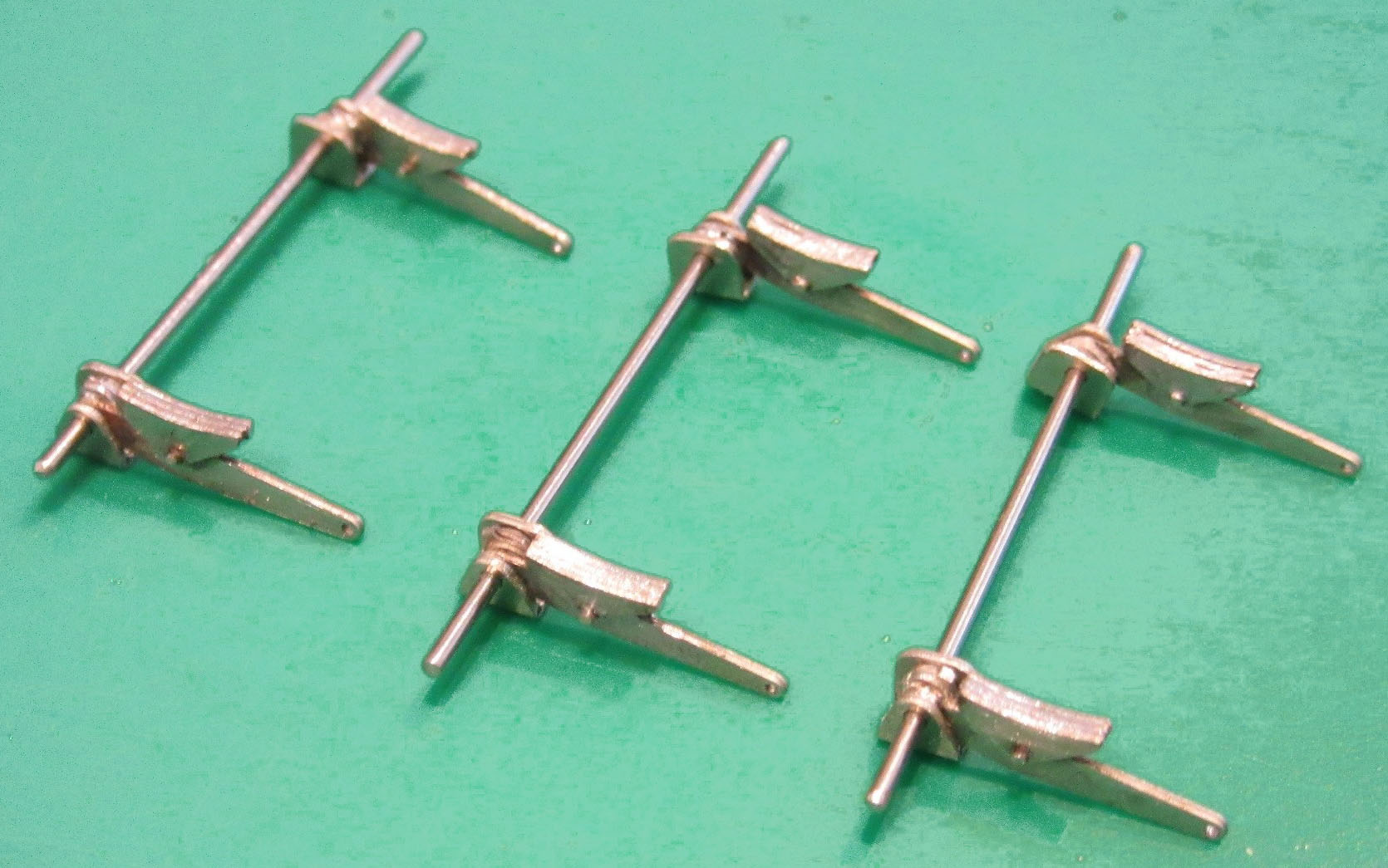
Replacement rods The rods can be fitted with either the fluted or plain side facing outwards depending on whether your locomotive had plain or fluted rods. The rods [L3-L6] are designed to be jointed in the prototypical manner, the 'tongue' and 'forks' for the joint being formed by half-etching. One hint to aid construction is to remove the two main parts of each rod from the fret but leave the tabs in place. The rods can then be folded back on each other which means that the alignment can be set and held in place while the parts are soldered together. Cut one pair of rods from the fret [L3]. Open out the crankpin holes with a 1.5 mm drill. Tin the back of each rod. Fold over the two halves of the rod as above ensuring that the holes align. This is probably best done by drilling a drill a hole using the same size drill perpendicular in a scrap piece of wood. Leave the drill in the hole in the wood. Place the rod over the drill. Place a little flux along the top surface of the rod and apply heat; the solder on the soldering iron will run down between the rods and join them. The secret is to apply only a little solder at a time. Solder will fill the “cusp” and give the impression of a solid rod. Repeat for the whole length of the rod.
Repeat for the other three rods [L4-L6]. Clean up each rod with files. Carefully blend the bosses into the front face of the rods. |
 |
|
There are two methods of forming the joint between the front and rear rods, either using a rivet or with a short length of 1.0 mm nickel silver wire. The rivet method is probably easier but results in an under-size collar on the front of the rod, the 1.0 mm wire gives the exact three inch collar. Rivet method Open out the joint holes very carefully with a broach or a tapered Swiss file to just clear the rivet. To stop solder flooding the joint apply a little oil to the surfaces not to be soldered - this will prevent the solder running into the joint. Keep the rear of the rod clean. Push the rivet through from the back so the head is tight up against the back of the etch. Solder can then be quickly applied with a very hot iron to the back of the rod to fix the rivet in place. File back the rivet at the front of the rod to leave about 0.5 mm proud. Wire method Open out the joint holes vary carefully with a broach or a tapered Swiss file to just clear the 1.0 mm wire. To stop solder flooding the joint apply a little oil to the surfaces not to be soldered - this will prevent the solder running into the joint. Keep the rear of the rod clean. Push the wire through from the front leaving about 0.5 mm proud. Solder can then be quickly applied with a very hot iron to the back of the rod to fix the wire in place. Clean off excess solder leaving enough to keep a strong joint. File back the wire at the front of the rod, again leaving about 0.5 mm proud. |
|
|
The front and rear rods are joined with a short length of 1mm nickel silver wire pushed through from the front and then cropped back on the rear leaving about 0.5 mm proud. Open out the joint holes vary carefully with a broach or a tapered Swiss file to just clear the 1 mm wire. To stop solder flooding the joint apply a little oil to the surfaces not to be soldered - this will prevent the solder running into the joint. Keep the rear of the rod clean. Solder can then be quickly applied with a very hot iron to the back of the rod to fix the wire in place. Clean off excess solder leaving enough to keep a strong joint. Open up the crankpin holes in order that the crankpin bushes will rotate in the rod. This can be done with a reamer, broach or a fine Swiss file. Check each of the crankpin holes in the rod is a good fit over your crankpin washers. At this stage it is better to err on the 'too tight' side rather than 'too loose'. |
|
|
Fitting the crankpins Fit your crank pin washers, rods and crankpin nuts to the wheels. At this stage you could also use a small piece of electrical wire sleeve in place of the nut (this does not come unscrewed unlike a proper 14BA nut!). If your wheel quartering is correct, then you should be able to roll the resulting chassis along the bench without it binding. If it is binding, check the quartering and check each crankpin in turn to see which one is stuck. If required, then slightly open up the crankpin hole in that rod. Do this carefully and a little at a time, you can easily remove material -putting it back is a lot harder. Once happy that the chassis rolls smoothly, the Hornby chassis block can be reinstalled and fastened using the front and rear bolts. The gear on the rear axle should mesh with the gear train from the motor but still retain a degree of springing. At this point if you plug the unconverted tender into the locomotive using the original Hornby cabling you can power the chassis from the tender to test, though obviously the tender will still be OO so you might need to be creative with the track/rolling road. |
 - - |
| Body modifications | |
|
Clearance for P4 wheels is tight behind the splashers on the chassis and some material will need to be removed. The casting has almost 1mm of thickness to the sides of the splashers. This work is best done with a carborundum disk in a mini-drill. Work slowly and carefully testing for clearance as you go. |
|
| Brakes | |
|
Using the original Hornby brake gear isn't an option so new brake blocks, hangers and linkage are provided on the etch. The brake components are mounted together and should be removed from the fret as a single unit. This makes folding and locating the parts together easier.
Locate and remove the locomotive brake
components [L13] from the etch, there are eight of these, you
need six; two are spares available as offerings to the carpet monster.
Ensure that you can get a piece of 0.45mm wire through the central holes
of the brake block and hanger, also that the top hole is opened to
0.8mm, doing this while the component is still flat is easiest using
either a drill or small broach. The brake assemblies are 'handed'; four
are available for each side of the locomotive. Thread a length of 0.45mm wire through the hole in the brake block, this will align the components together and form the bolt detail on the brake block. Cut this roughly off so it doesn't get in the way while soldering. Apply some flux and solder from the curved face of the brake block, this will run in between the components and join them securely.
Remove the assembled brake from the
surrounding etch with a sharp scalpel. Don't worry if the diagonal tabs
on the rear brake don't come off too cleanly, they are totally hidden
when on the locomotive or a small file will remove them. Locate the brake hanger brackets [L14] on the etch. Ensure that each of the holes is opened to 0.8mm, doing this while the components are still on the main etch is easiest using either a drill or small broach. The etch contains eight of these parts, giving two spares. Separate one of the brackets from the etch as photo to the right. |
|
|
Fold each end into a U-shape, ensuring that the sides are parallel and perpendicular to the end. The distance between the short side needs to fit a thickness of etch so you could fold the part around one of the frames which surround the brake components. The larger side spaces the brake hanger from the main frame. Then fold the two halves back on each other to make a W-shape. Apply a small quantity of solder to the part and then clean out the hole again to fit the 0.8mm wire. Feed a length of wire through the part and use this to hold it while you remove the cusps and any rough spots where the etch tabs joined. Note that these hangers are handed, the more angled face is orientated towards the outside of the chassis. Repeat this process six times until you have a complete set of brake blocks which can slide onto a 25mm length of 0.8mm rod.
Ensure that you have three of each handed brake block. |

|
|
The brake pull linkage [L16] comes
with matching half-etched linkage details which need to be applied to
the top and bottom of the main etch. It is easiest to tin the parts
BEFORE removing from the main etch
and to leave the pull rod itself attached to the main etch while this
work is completed.
The completed linkage should look like
this photograph. The ends of the brake cross members are over-long at
this stage and need to be filed down and rounded so that they can poke
through the holes in the bottom of the brake assemblies. The holes in
the brake hangers can also be enlarged slightly with a broach. The completed assembly should be able to be positioned so that the brake blocks are just clear of the wheel rims. Small pieces of wire insulation can be useful to stop these parts falling off prior to soldering. Solder the 0.8mm rod into the brake hanger brackets and apply solder to the ends of the brake cross members. Do not allow the solder to join the brake hanger brackets to the side frames as we want these to be removable. Avoid getting flux splashes on to the tyres of the wheels with a small strip of paper. Once happy with the position cut away the central section of the 0.8mm rod between the frames leaving about 0.5mm to protrude through the frame. This will allow the whole unit to be sprung off the chassis so that the wheels can be removed. Test fit the chassis on the footplate. The brake hangers will be hard up against the footplate. File and adjust as necessary. |

|
 |
|


|
Top of page Finishing touches for the locomotive Converting the tender |