6 Basic tender conversion
6.1 Remove all the parts (washers etc) from the tender frames [T1] and place them in your safe place. There are four spacing tabs, two at each end of the frames that need to be filed off if they are being fitted in the plastic Bachmann tender frames. Do not file them off if you are also building the replacement outside frames (actually it is not the end of the world if you do so don’t panic if you later decide to build the replacement outside frame).
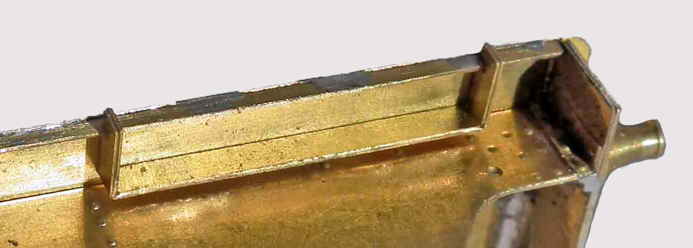
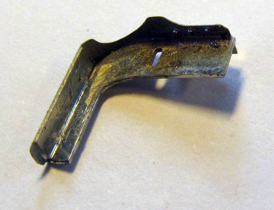
Fold up the tender frames [T1] to form a 'U'- section, taking special care with the narrow section on the bottom of the 'U' towards the front of the tender. Fold the outer half of the slotted axle bearing sections through 180 degrees back on themselves inside the frame. Note: the etched line is on the outside of the bend. To ensure a tight bend, squeeze the two halves together using a pair of pliers. (see Photo)
6.2 Open up the slots in the tender frames [T1] so that the tender axles slide freely without any slop.
6.3 Bend out the eight small ears on each side of frames at 90 degrees so they protrude out of the frames, bend down towards the track the four brackets through 90 degrees that will support the brake cylinder.
6.4 Cut off the plastic pillar which held the tension lock coupling at the rear of the Bachmann tender frames.
6.5 Remove the A frame towards the rear of the Bachmann ender floor and if you are fitting the etched front A frame then also remove the plastic. Also, the body retaining clips on the Bachman tender body at the front of the tender need to be reduced in width to clear the EasiChas frames using a craft knife or file.
6.6 Ensure that the new frames fit into the Bachmann tender. Secure in place using the Bachmann tension lock coupler screw in the rear hole. This is sufficient to hold the new frames in place. Remove the screw and tender frames.
6.7 Take the 6 axleboxes [T2] and, if necessary, open out the axle holes so that the axles rotate freely with a very slight amount of slop.
6.8 Fold up the 6 axleboxes [T2]. This is best done by placing the etch with the half-etched middle section perpendicular to the edge of a rule, or similar, to form a ‘T’ shape. Push down on each end of the etch so that it begins to wrap over each side of the rule. See photo.
6.9 Remove from the edge of the rule and push together between the fingers. Complete the bend by squeezing the two edges furthest from the bend with a pair of pliers (this is best done with a 2mm axle through the two holes which ensures two holes line up).
6.10 Assemble the rear tender wheelsets by firstly fitting spacing washer(s), then a bearing, then the second bearing, then more spacing washer(s) and finally the second wheel. Sufficient washers need to be fitted between the wheel and the bearing to ensure there is minimum sideplay. For guidance for P4 two full width and one half-etched washers per side is recommended on the rear axles, one and a half on the leading and one none on the centre. For EM a single washer on the rear is sufficient. For less than 3ft curves, fewer will be required.
A tip to check the first wheel fitted is running true, is to balance them on a steel rule holding the axle with a file and move to left and right spinning the wheels, and wobble can be corrected by ‘twisting’ the wheel with finger pressure and then re-checking. See Photo.

6.11 Mount the wheelsets in the ‘U’ slots on the frames with the axleboxes on the outside of the frame.
6.12 Take the thin 8 thou steel spring and put a 2mm right angle bend in the end, cut to 77mm long and then slide the thin 9 thou steel spring wire through the frame ears and holes in the axleboxes (this is a bit of a fiddle!). Bend over the end of the wire to retain. See Photo.
6.13 Fit the frames to the Bachmann tender, locating and refit the tender top. Secure in place with the original coupling post screw through the rear hole in the frames. This is sufficient to retain the frames.
6.14 Ensure that the tender runs smoothly and that all the axleboxes are free to move up and down. Adjust the Bachmann tender coupling to suit your model curves.
6.15 Re-assemble the tender. The loco tender coupling has quite a bit of slop in it. If desired, solder a 2mm washer to the bottom of the coupling link over the rear hole. This then slides onto the tender pin without slop.
The basic tender conversion is now complete, but significant visual improvements can be made by replacing the tender brake gear, see section 8.
Replacement tender frames
The Bachmann tender frames are spaced a lot further apart than on the prototype due to an over allowance for the thickness of 00 wheels and to the thicker frames. This results in the axleboxes being too shallow. The replacement frames, top plate, drag and buffer beams fit in place of the Bachmann originals, and in turn, the EasiChas frames fit to the underside of the replacement frames. The replacement frames still allow the tender to negotiate 3 foot curves in both EM and P4.
There are two types of tender underframes. The type that comes with the Bachmann loco is the last Bowen Cooke type, referred to in Talbot’s book as BC4. An earlier version, BC3, had the same body but the frames were to a Whale design and these tenders were common on the G1, G2 and G2A locos. A separate etch for these frames to produce a BC3 tender is available from Brassmasters (ref B244).
9.1 Push through all the rivets in the tender frames [F1]. There are a lot of them.
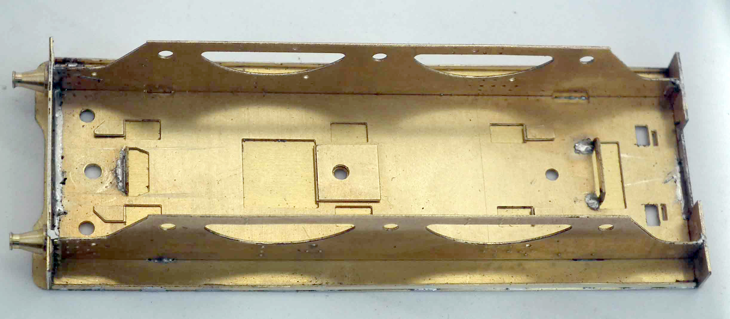
9.2 Fold over the five tabs on the base of the tender frames [F1] back on themselves (see photo). Ensure they are completely flat.
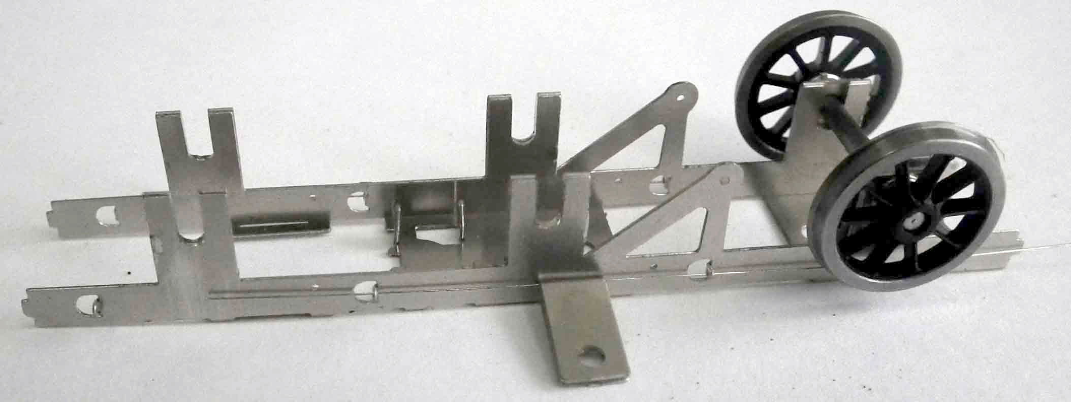
9.3 Fold up the sides of the tender frames to 90 degrees, then fold up the two mounting guides to 90 degrees. Strengthen these last two with solder. (note photo shows BC3 frames but construction is identical)
9.4 Make sure that the Bachmann adjustable tender coupling will fit through the gap of the leading mounting guide – it will probably need a gentle dressing with a file.
9.5 Reduce the head diameter of the Bachmann body retaining screws by holding them in a pin chuck and rotating them against a file
9.6 Ensure the four tabs on the top of the frames [F1] engage in the slots in the tender footplate [F2]. Solder the two together through the various slots between the frames not along the side of the frame (otherwise this may affect the fitting of the rivet strip later). Make sure the top face of the footplate is completely flat.
9.7 There are two types of buffer beam, the normal flat type and the riveted type which was fitted to a few tenders. Identify which of the two types is required ([F3] for the flat type, [F4] for the riveted type.
9.8 Take the buffer beam back [F5] and push through the rivets. Solder the buffer beam front [F3 or F4] and the buffer beam back [F5] together.
9.9 If re-using the Bachmann plastic buffers, push through the rivets on the back of the buffer bases [F6] and solder them in place on the buffer beam.
9.10 AT THIS POINT IT IS IMPERATIVE THAT YOU OPEN OUT THE HOLES IN THE BUFFER BEAM TO SUIT YOUR CHOSEN BUFFERS. If using replacement brass buffers, solder to the bufferbeam and file back so the rear of the bufferbeam is flush.
9.11 Solder the buffer beam assembly to the tender base and frames ensuring the it is the correct way up (the buffer holes should be towards the bottom of the buffer beam when fitted). You will probably also have to open the hole in the brass buffers out with a 0.5mm drill as solder will have flooded the hole.
9.12 There are two different types of draw beam front in the EasiChas kit, a cut-away one for use with the Bachmann coupling [F7] and the full beam [F8] if a different coupling is being used. Solder the appropriate draw beam front to the draw beam back [F9]. If using the full beam, solder on the drawbar pocket casting [F10].
9.13 Solder the draw beam assembly to the tender base and frames.
9.14 Solder the left hand rivet strip [F11] vertically to the rear end of the left hand side frames butted up against the buffer beam back and the footplate. Repeat for the right hand rivet strip [F12] on the right hand side.
9.15 Take the two footplate valances ([F13] left hand and [F14] right hand). If you are not building a loco with a tender cab, file off flush with the valance edge the two triangular pieces.
9.16 Take the valance jig [F15] and bend to a U shape along the bend lines. Make sure that the valances fit in the slots.

9.17 Position the left hand side valance [F13] in position in the half-etched recess on the left hand edge of the footplate with the triangular piece (or the place where it was) towards the back and away from the footplate, and hold upright using the jig. Photo shows jig in place to hold the valence at 90 degrees during soldering.
9.18 Tack solder the valance in four or five positions along the footplate, moving the jig as you do so. Do not try to solder the valance in one go as it will distort with the heat. Carefully fill in the gaps between the tacks allowing the valance to cool between each one. Repeat for the right hand valance [F14].
9.19 Open out the hole each side in the rear lower edge of the frames to clear 0.7mm wire. Insert a piece of 0.7mm wire through the holes, ensure the frames are parallel and solder the wire to both frames. Trim back the wire flush with the frames.
9.20 Tack solder the left hand frame strengthening strip [F16] in place along the bottom of the left hand frame in four or five places ensuring the curved corner is at the front and to the outside. Do not try to solder the strip in one go as it will distort with the heat. Carefully solder the strip between the tacks allowing the strip to cool between each one. Repeat for the right hand strengthening strip [F17].
9.21 Take a footstep [F21] and solder in place to the step back [F19] with the half-etched edge towards the bottom, in the slot in the footstep back, take time to position it accurately. Then take the left hand step outside edge [F18] and, starting from the top, curve it to fit round the outside edge of the step back [F19]. Solder in place making sure the back edge is flush with the back of the step back.
9.22 Turn over the very end of the outer edge to form the end of the footstep tread.
9.23 Take the left hand step inside edge [F20] and curve it round the inside edge of the step back. This is not easy and will require some patience.
9.24 Take a piece of softwood and with a small screwdriver make an indent in the wood large enough to accommodate the tab on the back of the left hand step inside edge [F20]. With the tab in this hole place the footstep assembly on the wood and solder the inside edge in position making sure that the back edge is flush with the back of the step back.
9.25 When your patience and sense of humour have returned, repeat for the right hand step using the step back [F19] the footstep [F21], the right hand outside edge [F22], and the right hand inside edge [F23]. Fit to the tender frames behind the drag beam.
9.26 If you are re-using the Bachman buffers, gently pull the buffers from the rear of the Bachmann tender frames. File away the spigot of the buffer housing and the buffer rod from the side until it fits in the hole in the buffer beam and misses the side frame. This will mean removing about 50% of the spigot.
9.27 Attach the buffers to the buffer beams on the replacement frames using cyanoacrylate glue or epoxy resin.
Note - a better method is to fit brass sprung buffers available separately from Brassmasters (ref A217)
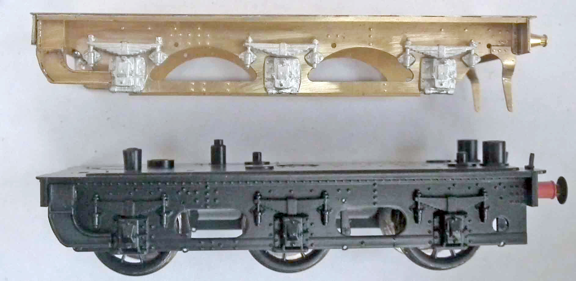
9.28 Cut the axlebox and spring hanger assemblies from the Bachmann frames using a piercing saw. Reduce the thickness of the back of each assembly, and then attach to the replacement frames (see photo).
Note - a better method is to fit new whitemetal axlebox and springs - available separately from Brassmasters (ref B245) (see photo which is actually of a BC3 framed version)
9.29 Solder the two footstep assemblies to each side of the frames.
9.30 Take the guard irons ([F24] for the left hand side and [F25] for the right hand side), push through the rivets from the rear, curve to shape and solder in position on the inside of the tender frames.
9.31 If using with the EasiChas tender frames, solder an 8 BA nut in the recess on the top centre of the tender footplate [F2]. Solder the Bachmann loco coupling nut over the hole towards the front of the footplate.
9.32 Remove the Bachmann fall plate from the tender body by unbending the two tabs. Insert the two tabs in the thin slots in the new footplate and bend over the tabs.
9.33 Fit the locomotive coupling in place using the original Bachmann screw and then attach the EasiChas frames to the footplate frame assembly using an 8BA screw.
Finally, fit the tender body in place by insetting the two tabs into the slots at the front of footplate and securing in place using the two original Bachmann screws through the two rear holes.