Tools Required
A selection of cross head and normal miniature screwdrivers
Small pliers
Small plastic bags and labels to identify parts and screws when dismantling
Small files
Soldering iron (for electrical connections)
A steel rule
Back to Back wheel gauge
Plastic solvent, superglue and epoxy resin (24 hour and 5 minute)
The Mazak chassis block is very soft and the retaining screws are fine pitch. If any screws are incorrectly inserted (i.e. a self-tapper into a machine screw hole) or they are over tightened the thread will be stripped and correct fastening will be impeded.
In all cases, bag and label all small parts and source of screws as soon as removed (they are all different) - trust us on this one!
Dismantling the Locomotive
4.1 Firstly check that the locomotive works and the motor runs because the warranty is about to be invalidated! With pliers, pull out the electrical plug under the tender and release the locomotive from the tender by manipulating the drawbar, plug and wires.
4.2 Unclip the brake pull rods from each brake block hanger so that the pull assembly hinges on the rear brake cylinder cross shaft. Carefully unclip this cross shaft by bending the shaft with pliers. Unless you are very careful, the end pips will break off.
4.3 Unscrew the front (two screws) and rear screw, pull the chassis vertically to remove the chassis from the body. The rear screw releases the tender drawbar. Make sure you don’t lose this.
4.4 To remove the keeper plate (with brakes attached), remove the remaining screws. Remove the wheel sets from the chassis, unscrew the machine screws from the wheels and remove the coupling rods. Put the screws back into the wheels for safekeeping.
4.5 Remove the glued-on sandboxes (by twisting with pliers) and sand pipes. Store these for use later.
4.6 Remove the screw from the pickup PCB contact plate in the bottom of the chassis and pull out (the wires are quite long). Unsolder or cut the wires to remove the PCB. Tuck the wires back into the hole for now. There are slots in the EasiChas and keeper plate to feed the wires through for the new pickups later in the instructions.
4.7 Before carrying out the next steps, cover both the tender link electrical socket and the gear train in the chassis with tissue to prevent swarf getting into them.
4.8 File off the pips in the chassis block behind where the sandboxes were fitted and also those on the underside of the chassis block at the rear. The footplate support bracket in the middle of each side also needs filing back to clear the EasiChas frames.
4.9 The raised area on the Bachmann chassis around the third axle slot needs to be removed, by filling, for P4, and around both the second and third axle slots for EM.
4.10 Finally, the cast brake shaft brackets and representation of the central activating cylinder need to be removed from the Bachmann chassis block using a piercing saw and files (see photo of one side completed).

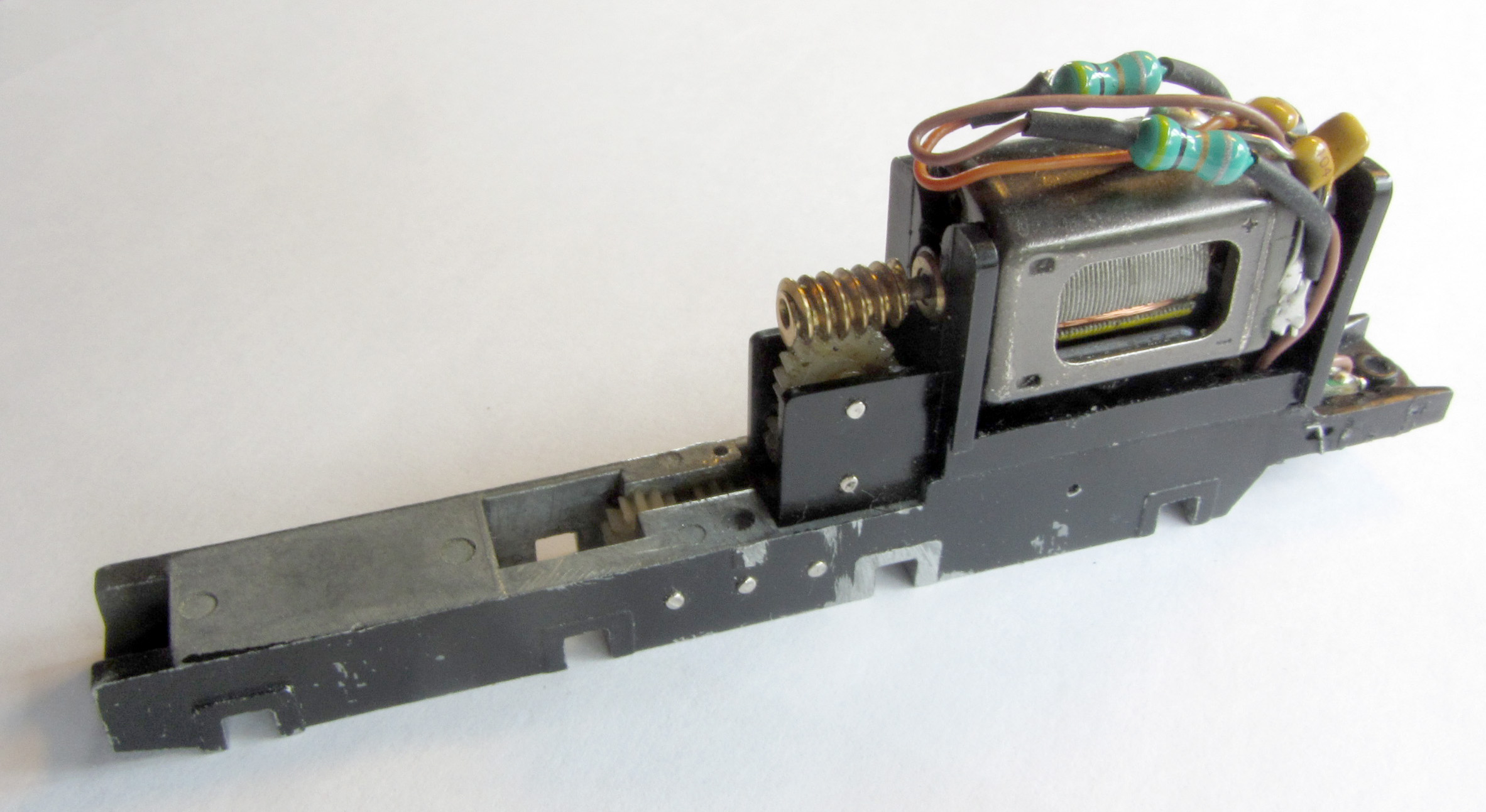
4.11 The chassis now looks like this:
4.12 De-grease the chassis sides.
4.13 Take the locomotive body and remove the screw beneath the backhead. Remove this and store it carefully. The boiler has to be released to remove the front coupling arrangement smokebox see section 7.9.1 for details how to split the model.
4.14 We have found that only one drive gear is required on the third axle. Using two causes problems with quartering and is unnecessary with properly fitted coupling rods.
Hold the one of the wheels with wheels with a gear wheel and with a twisting pulling motion pull off the wheels from the axle. Also, slide off the brass bushes.
Place the axles in a vice such that the gear wheel is supported on the vice sides but the axle is loose. Tap the axle with a hammer or similar and the gear wheel will slide off the axle.
If you do not have a vice, use a pair of pliers on one side of the gear wheel, gently slide the plastic gear down and off the axle by holding the axle vertical and pressing down. It is very important not to damage this gear.
Dismantling the Tender
4.15 Taking the tender, unscrew the two rear screws behind the buffers. The front is secured by two clips that extend vertically from the front tender bulkhead down through the tender floor/platform (chassis top). Some have suffered from stray glue so need pressure from below to free them. With the rear screws now removed lever up the rear of the tender and the front clips will release the body.
4.16 Spring the tender side frames apart to release the brake pull rod assembly. Again, spring the tender side frames apart to release the wheels. Remove the rear tension lock coupling (put a screwdriver below it and twist) to reveal the screw holding the coupling pocket. Remove this.
4.17 You will now have a box of bits and an invalid Bachmann guarantee!
4.18 Wash your hands as you will have grease on them from stripping the chassis and the etches should be kept as clean as possible.