5 Basic loco conversion
5.1 If you are using Alan Gibson wheels you may need to drill the crankpin holes using a 0.65mm drill. The hole must be perpendicular to the wheel. The following will prevent problems with loose crankpins. Countersink the rear of the crankpin screw holes using a 3mm drill and half screw the 12BA screws home, if the crankpin hole is not fully clear of the center plastic boss then cut some of this away to aid countersinking. Using 24 hour epoxy, smear the remaining thread and screw the 12BA screws home. Smear a little epoxy over the head for additional security but there should not be a big blob that will catch on wheel rotation. Leave in a warm place for 24 hours to set. This will retain the screws and stop them from rotating. See photo (before the epoxy was applied) of a larger diameter but similar wheel.
Now is also a good time to ‘fill in’ behind the 'H'-section spokes with black plasticard for those segments fitted with balance weights – different axles had different balance weight arrangements and there were variations, especially on the driven (flangeless wheel) axle. Study prototype photos. Do not copy the Bachmann wheels as this is incorrect for at least the driven axle.
We cut a piece of plasticard 4mm wide and made ‘triangles’ out of this and carefully fit them from behind, fixing with super glue. This is a time-consuming job, but if you do not do it now you will regret it because it is very noticeable on the running model!
5.1.1 Before stating on the main EasiChas frames it is necessary to make a couple of decisions.
5.2 The bottom of the Bachmann chassis block is a lot lower than the bottom of the frames of the G2 so it has been necessary to lower the bottom edge of the EasiChas frames between the wheels to partially hide the chassis block. The dimension used is not without precedent as we have used the frame depth from the 0-8-2 and 0-8-4 tanks that had deeper frames to support the additional weight of the tanks. However, if you want the correct height to the frames, there is a half-etched line on the back of the frames between the wheels marking the correct height, which will need filing back to.
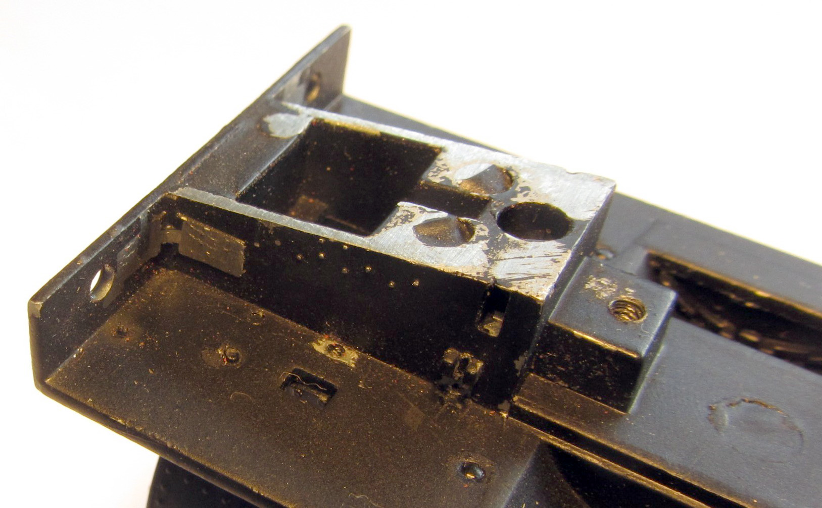
5.2.1 The frames include the brackets for the second brake shaft between the second and third axles. These were fitted to G2 and G2A locos. If you are modelling a G1 or G2 with only one brake cylinder, these brackets need to be removed. Do this by cutting through the two legs of the bracket each side (see photo with the cut line shown dotted). If you wish to use replacement rods it is best to do this now, certainly do this before fitting the wheels to the axles as this will make checking the rod’s length difficult (see 7.1)

5.2.2 The EasiChas includes replacement locomotive buffer beam brackets. To use them requires the cast brackets behind the buffer beam on the Bachmann footplate to be removed. This is quite easy to do with a burr in a mini-drill but can also achieved with drills and files See photo of the finished job.
As an alternative, the leading part of the EasiChas frames can be cut away to clear the original casting on the footplate. For this option, cut back the frames to the half-etched lines on the inside of the frames.
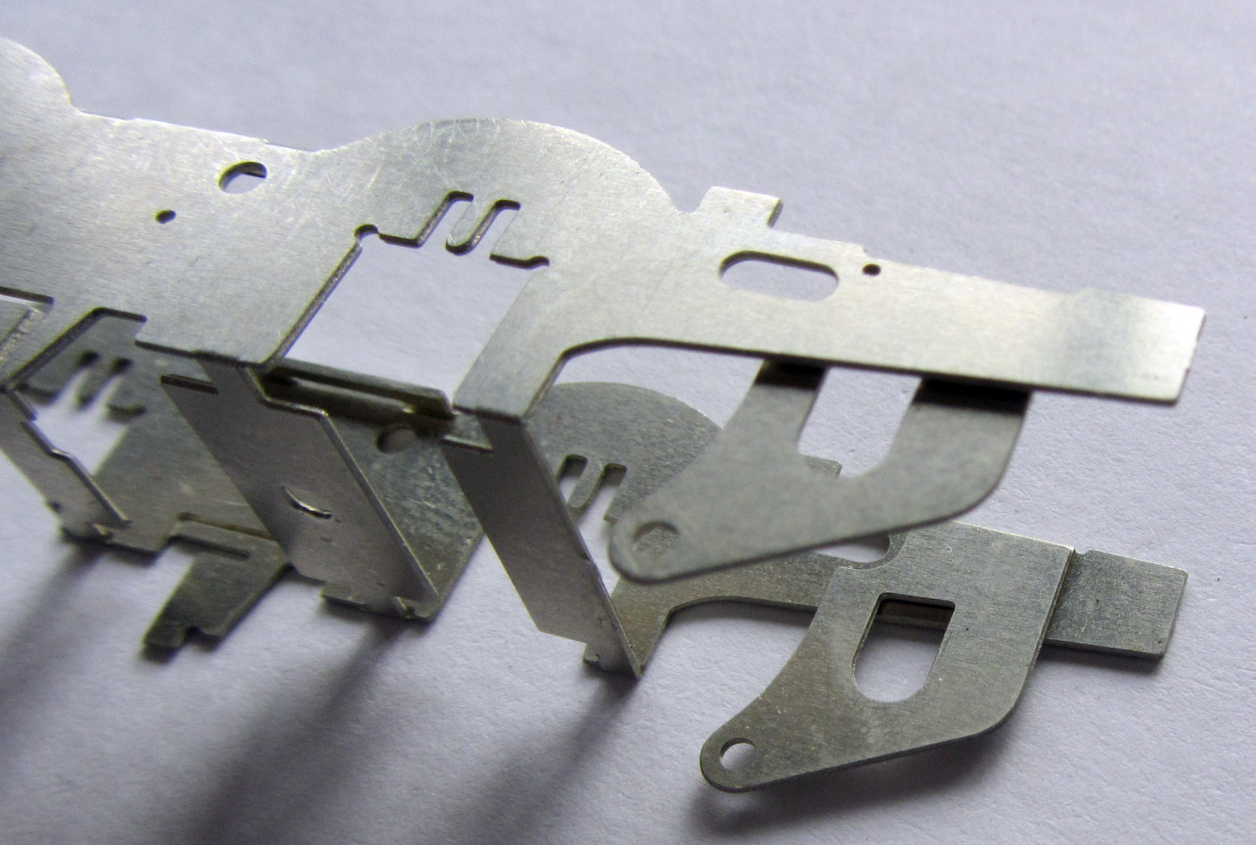
5.3 Remove the loco mainframes [L1] and clean up the residual tabs with a small file. With a riveting tool or sharp implement push through the half-etched rivets at the rear and centre of each frame.
5.4 Place the frames flat on the bench and with a thin metal rule fold to produce a ‘U’ section.
Either again using a ruler or using a strong pair of pliers, fold up the small top sections along the edge of the main frames at 90 degrees, and then on the two top sections each side towards the front which have bend down sections, bend these down (see photo with these folded down on back frame).
For added strength, solder these to the frame.

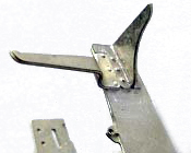
5.5 Fold over the rear brake shaft brackets between the frames, with the fold line on the outside. These should lie against the frame – solder or glue (cyanoacrylate glue or epoxy resin) may be used to encourage this. See Photo
5.5.1 Ensure the mainframes fit over the original Bachmann chassis. The frames should sit parallel to the Bachmann frames and not be ‘splayed’ out at the top. If necessary, file the top sections back to ensure this. Remove the mainframes. There is a portion of dummy framing attached under the Bachmann Mazak footplate, remove the front brakes and sandpipes from this by snapping them off – put them in a safe place. It makes fitting the etched frames easier by removing the residual pips etc from this area of the Mazak (file them off).
5.5.2 Check the fit of the brass bearings into the slots in the mainframes. If tight, using a smooth sharp file, lightly file away the cusp equally on both of the edges of the slots until the bearing slides up and down with no binding. It is very important that too much metal is not removed resulting in a sloppy fit – no side play whatsoever is the aim, just a smooth sliding fit.
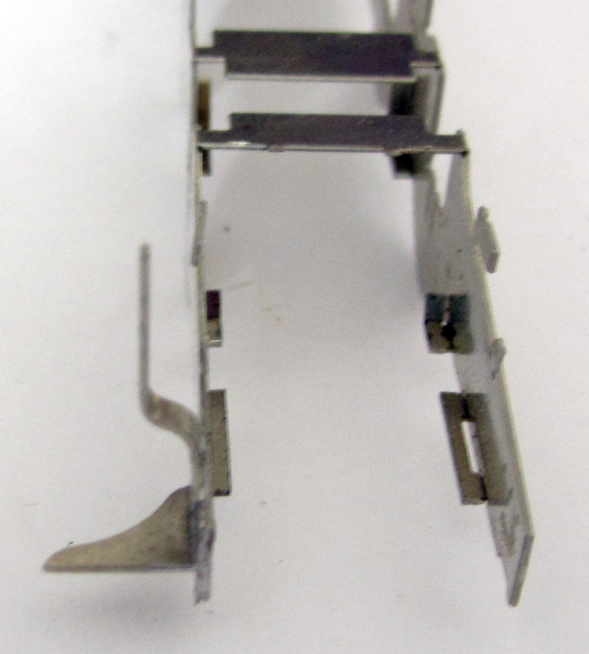
5.5 Identify all the items within and attached to the outside of the keep plate [L2], remove them and store them safely. Remove the keep plate [L2]. Fold up the four U shaped pieces between the leading and second axles and the second and third axles. Ensure they slide between the mainframes [L1]. Fold down the eight axle keep plates along each side of the keep plate (G2 variant is shown with the second brake cylinder bracket).
5.6 Test fit the keeper plate and the chassis to the Bachmann chassis
5.5 Unless you are using the replacement etched brake gear, fold up the ‘cups’ on the frame sides and keep plate front that will hold the Bachmann plastic brake hangers so that they form a flat bottom gentle ‘L’-shape with a slight sloping upright (see picture in section 5.18 lower when formed).

This fits between the frame and the keeper plate with the tongue facing forward in the correspondingly shaped cut out.

IMPORTANT - Carefully examine the bearings because they are not symmetrical. It can be seen that the flange on one side of the slot is wider than the other side. For EM gauge, the bearings need to be mounted in the frames with the thicker flange towards the centre of the frames. For P4 gauge, the bearings need to be mounted with the thinner flange towards the centre of the frames. Increased side-play on the drivers can be obtained by having the thin side of the bearings on the outside or rubbing off the circular beading round the axle hole. For EM gauge, it will be necessary to file off the raised rim on the inside face of the bearings to ensure the bearings move up and down freely.
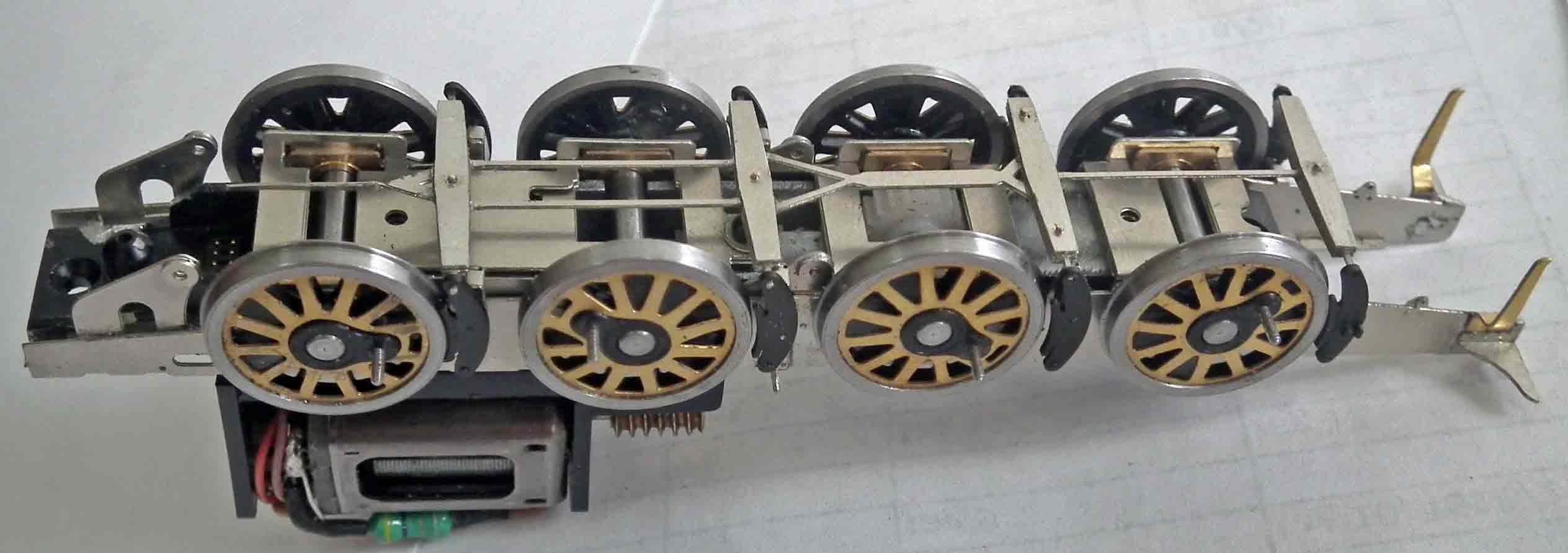
5.8 Again, fit the mainframes to the Bachmann chassis, place the bearings in the slots and check for easy movement. See photo.
5.9 Temporarily fit the keep plate, using the original Bachmann screws and lower keeper plate, plus washers [L4]. Ensure the bearings slide to the bottom of each slot in the keep plate. Rather than use the washers, the screws could be shortened.

5.10 Take the new 3mm axles and test fit them, firstly in the axleboxes (if tight ream them out to 3mm using a reamer or, if you do not have one, a small round file, a precision drill or a broach), then place each through the axleboxes and through the “slots” in the Bachmann chassis block. If the axles catch the side of the Bachmann chassis block file away the offending part of the block. The Mazak is not the most stable material so it is surprising how much metal may need to be removed from some axle slots. This is much easier to do at this stage than when the wheels are mounted or at an even later stage.
5.11 Take the axles and file the sharp edges of the end to a rounded profile. Use a drill bit of around 5mm diameter to chamfer the rear of each wheel axle hole. These two actions help the axle to ‘centre’ in the wheel when they are pressed on.
5.12 Fit the Bachmann axle gear wheel onto the new axle by gentle pushing the gearwheel onto the axle, ensuring that the worm wheel is centred on the axle so the gear wheel engages properly, and the same amount of axle protruding each side of the chassis when it is fitted. Personally, we roll a file edge pressed very hard against the axle in the position the gear will sit before fixing, thereby ‘knurling’ the axle and providing extra grip for the gear, but this is probably not necessary!
5.13 Mount the bearings on all axles the correct way round (see section 5.7), then any spacing washers required (there will be about 0.8mm lateral movement of an axle with no washers in 18.83 gauge – so not many washers are required. For 18.83mm gauge we suggest one full washer is fitted each side of axles 1, 3 &4, for EM one half washer on each side of the leading and trailing wheels, and finally press the wheels on the axles and quarter the wheels, remembering that the flangeless wheels should be fitted to the axle with the gearwheel. For these ex-LNWR locos they should be quartered with the left hand wheel leading the right hand wheel by 90 degrees. However, as you will never see both sides at the same time, and commercially available quartering jigs have the right hand wheel leading, it won’t be the end of the world if the right hand wheels lead.
5.14 Place the bearing springs over the tongues on the frames (a small spot of grease in the spring helps to retain the springs in place when fitting and removing the wheels), fit the wheelsets into the main frames and attach the keep plate and ashpan. See Photo. Check that the motor turns the driven wheelset with no sign of any binding by applying power to the motor. Remove the springs and put them safe while working on the rods and checking for free running.
5.15 If fitting the buffer beam brackets to the frames, push through the rivets in the bracket bases [L5 left hand side, L6 right hand side] and attach to the frames ensuring the bracket web [L6] fits through the slot in the bracket base and frames. If intending to use working sprung buffers on the front of the loco the bracket webs [L6] will need to be cut back to clear the buffer tail (see photo). Attach the buffer beam web [L7] to each side of the frames.
5.16 Attach the brake shaft bracket strengthening rings [L11] to the outside of the brake shaft brackets on the rear of the frames and, if the loco has two brake cylinders, to the brake shaft brackets on the keep plate.
5.17 Identify the footplate bracket bases [L8] left hand side and [L9] for the right hand side (the corner cut-out is at the bottom and towards the rear). Position the appropriate bracket base over the slot in the frames and hold in position with the footplate bracket web [L10] and secure in place.
Repeat for the other side. See below and 7.2.5

5.18 Push through the rivets in each guard iron ([D1] for left hand side and [D2] for the right hand side) and form to a slight ‘S’ shape. Glue, or preferably solder, to the frames, with the curved face towards the rear, to the chassis frames immediately behind the buffer beam bracket. See photo.
If you wish to fit the replacement etched brake blocks and supporting brackets, now is a good time to jump to section 7.2 and assemble the sequence from 7.2.1 to 7.2.6.
Coupling rods
5.19 Fit the Bachmann coupling rods with the eight bushes provided. This will require each hole to be opened up to with a rat-tail round file to accept the bushes, if you are careful these can be an interference fit. If not the bushes have to be soldered or glued with epoxy centrally in place. If needed, open out the bushes using a reamer, broach or file to take the Gibson crankpin bushes - see photo
A finer scale solution is to solder up a new set of coupling rods, but this of course takes longer (see section 7.1).

5.20 Fit the rods and temporarily secure with a piece of electrical wire sleeve (does not come unscrewed unlike a proper 14BA nut!). Check that all the wheels now turn without binding when power is applied to the motor and are quartered correctly. Be careful as you tighten the retaining screws as it can distort the chassis just slightly which results in the axleboxes not sliding freely (don’t forget to add the washers under the screw heads if using them). See photo.
5.21 Fit the eight springs above the axleboxes to achieve a fully sprung chassis. Note that the driven axle should not drop too low to allow it to drop out of mesh with the gear above. If this is happening, solder or glue a packer onto the top of the keeper plate to stop this as it will damage the gears if allowed to repeatedly occur.

Electrical pick-ups
5.22 Loco pick-ups. It is not possible to re-use the Bachmann pick-ups so you will need to fabricate your own. Many modellers have their own ideas on pickups, this is how we do it.
Using a copperclad sleeper (cut to fit between the keeper plate springs) and 33 swg phosphor bronze wire (not supplied but available from Eileen’s Emporium), wind a ‘spring’ shape with extended end. We clamp a fine screw driver in the vice and holding the wire one end in the fingers and the other in a pair of round nose pliers, form the spring round the screw driver shaft. Note one pickup is wound clockwise, one anti-clockwise. There is only just over 3.2mm clearance between the keeper plate and the brake pull rods and cross shafts on this loco so it is wise to thin the paxolin sleeper to about 1.5mm – it just gives you that little bit more room for the pickup wires. Solder to the copperclad (gapping it first!) as the photo above. If you are using the existing Bachmann wires that you carefully tucked inside the chassis block it is advisable to enlarge the hole in the keeper plate and ashpan to allow these to come through easily – do not try and force them through small holes or it will distort the chassis.
5.22.1 Electrics. If you are DCC, you will need to use the jump leads to the tender just as supplied by Bachmann and put the de-coder in the tender. If you are DC, the electrical jumper can be made redundant by bridging the solder blobs on the top of the plate where the jumper pushes in. Join each outer solder blob with the one adjacent to it. This will allow you to use the original wires to the Bachmann pick-ups to feed the motor through the resistors that are factory fitted.
5.23 Glue the paxolin pick-ups to the chassis keeper plate in the positions shown (some will need shaping around the screw fitting points) in the photo below so they gently press on the wheel flanges. Most are virtually invisible behind the brake blocks. Test the polarity and direction of travel with another loco and connect together with thin rigid wire and to the motor wire. Test run.
5.23.1 If the final gear jumps out mesh, then the keeper plate is not retaining the bearings tight enough against the top of the bearing slot. Adjust fitting and if necessary reduce the downward play by soldering a piece of scrap wire above the keeper plate thereby reducing the amount of vertical play possible.
5.24 When happy, remove the temporary crank pins, shorten the bushes and fit the crankpin bushes (note, if you are going to fit new coupling rods as per section 7.1 do not shorten the bushes).

Brakes
Note – if you are replacing the brake blocks and hangers with the etched version go to section 7.2
5.25 The Bachmann plastic brake hangers are single whereas the prototype had double hangers around each brake block. If you decide to fit these plastic brakes, then carefully cut the brake blocks and hangers off the Bachmann keeper plate and footplate casting by sawing next to the main part of the centre solid section. Once the saw cut is started hold the brake block (not the bigger keeper plate) as they will ping off across the room! See photo of a similar operation on a 4F. Keep safely for later use.
5.26 Clean up the cut line on the plastic brake hangers to ensure there are no raised edges and if necessary shorten the hanger back ‘studs’ (that fit in the ‘cups’) so they line up with the wheel treads. Remember the chassis is sprung and the wheels will move upwards under the locomotive weight.
5.27 Attach the two brake hanger assemblies cut from the footplate to the leading brake hanger attachment point each side using cyanoacrylate glue or epoxy resin.
5.28 Then attach the remaining brake hanger assemblies to the brake hanger attachment points using cyanoacrylate glue or epoxy resin. See photo 5.30.6 after fitting the cross shafts.
5.29 When it comes to the brake pull rods there is a choice of the amount of detail you may want to include. The instructions cover all, but feel free to miss out what you do not want to add.
i. Just have the pull rods and brake shafts
ii. add overlays to the pull rods and pull rod levers
iii. include the brake cylinder levers
The instructions cover the full assembly as in iii., but any items can be omitted.
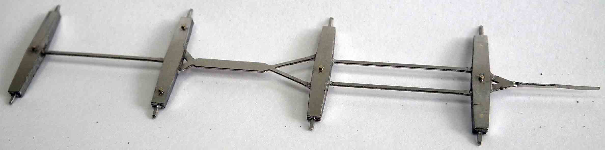
5.30 If your locomotive has only the rear brake cylinder, there is only one continuous brake pull rod to assemble.
5.30.1 Take the brake pull rod etch [L12], and twist the rear section though 90 degrees (see photo 5.30.2).
5.30.2 If you are fitting the brake beam overlays and wish to replicate the slot in the front beam, file the front edge of the of the front beam on the brake pull rod [L12] as shown on the diagram in Appendix 2. Identify the eight brake beam overlays fitted to the top and bottom of the brake pull rods [L13 for the front beam, L14 for the second beam, L13 for the third beam and L15 for the rear beam]. Using a piece of 0.5mm wire through the holes, solder or glue the top and bottom overlays to the pull rod. Trim back the wire almost flush on top of the beam but leave a small section on the bottom to represent the nut. For the one continuous brake pull rod version fill the two blind holes on the rear overlays (it just has a bolt in the middle), for the two part pull rod version there are two bolts through the outer holes and the centre one needs filling. See photo of one part pull rod.
5.30.3 If you are fitting the brake cylinder lever, cut three pieces of 1.2mm dia tube 6, 2 and 3.5mm long and cut a piece of 1.0mm wire about 15mm long to fit through the brake shaft brackets. Clean up the ends of the wire and tube and make sure the tube will slide over the wire. Adjust by filing back the wire so it is flush with the outside of the brake shaft brackets on the rear of the frames.
5.30.4 Take the brake pull rod overlays [L16] and add to each side of the brake pull rod lever [L17].
5.30.5 Assemble the brake shaft by pushing the wire through the right hand brake shaft bracket then first placing the 6mm length of tube over the wire, followed by the brake pull rod lever [L17] with the lever at the bottom pointing to the left, followed by the 2mm length of tube, followed by the rear brake cylinder lever [L18] with the lever to the right and upwards followed by the 4mm long piece of tube and finally push the wire through the brake shaft bracket in the left hand frame (see drawing). DO NOT SOLDER/GLUE the assembly together at this stage.
5.30.6 Spring the brake pull rods into place between the brake hangers.
5.30.7 Align the half-etched end of the brake pull rods and the brake pull rod lever, cut back as necessary and join together with solder or glue.
5.30.8 Rotate the rear brake cylinder lever [L18] until the piston rod is vertical. Carefully apply solder or glue to the assembly to lock the levers in place on the tube and wire assembly ensuring that the brake shaft can still be sprung out of the brake shaft brackets. (See drawing) Note that the actual brake cylinder was some 7” off centre on the prototype which is why the vertical actuating rod is so positioned and also the reason for removal of the Bachmann casting (which is also incorrectly shaped).
5.30.9 To remove the brake pull rods, first unclip the brake hanger assemblies from the end of the support wire and then unclip the brake shaft by springing the brake shaft brackets apart.

5.31 If your locomotive has two brake cylinders there are two brake pull rods to assemble then follow this section, otherwise jump to section 5.32.
5.31.1 Take the rear brake rear brake pull rods etch [L19] and twist the rear section through 90 degrees (see photo).
5.31.2 Identify the four brake beam overlays fitted to the top and bottom of the rear brake pull rods, [L13] for the front beam, and [L15] for the rear beam. Using a piece of 0.5mm wire through the holes, solder or glue the top and bottom overlays to the pull rod. Trim back the wire almost flush on top of the beam but leave a small section on the bottom to represent the nut. (see photo).
5.31.3 Follow instructions 5.29.3 – 5.29.6 for the rest of the assembly of the rear pull rods and brake shaft.
5.31.4 Take the front pull rods [L20] and make sure the slot at the end will allow a 0.4mm thick etch will pass along it. If you are fitting the brake beam overlays and wish to replicate the slot in the front beam, file the front edge of the of the front beam on the brake pull rod [L20] as shown on the diagram Appendix 2
5.31.5 Identify the four brake beam overlays fitted to the top and bottom of the front brake pull rods, [L13] for the front beam, and [L14] for the rear beam. Using a piece of 0.5mm wire through the holes, solder or glue the top and bottom overlays to the pull rod. Trim back the wire almost flush on top of the beam but leave a small section on the bottom to represent the nut (see photo of one part pull rod 5.30.2).
5.31.6 Cut two pieces of 1.0mm diameter tube 5.2mm and 5.6mm long and cut a piece of 1.0mm wire about 15mm long to fit across between the brake shaft brackets. Clean up the ends of the wire and tube and make sure the tube will slide over the wire. The wire should be flush with the outside of the brake shaft brackets on the keep plate.
5.31.7 Attach the brake shaft lever overlays [L21] to each side of the front brake shaft lever [L22]

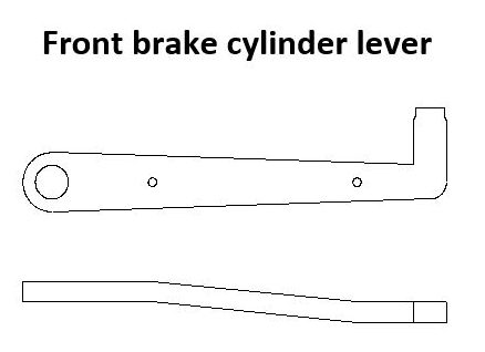
5.31.8 Take the front brake cylinder lever [L23] and bend at the marks as shown in the diagram.
5.31.9 Assemble the brake shaft by pushing the wire through the right hand brake shaft bracket in the keeper plate, then first placing the 5.2mm length of tube over the wire, followed by the brake cylinder lever [L23] with the lever to the right and the spigot towards the top, followed by the brake shaft lever [L22] with the lever at the bottom pointing to the left, followed by the 5.6mm length of tube, and finally pushing the wire through the brake shaft bracket in the left hand side of the keep plate (see drawing). DO NOT SOLDER/GLUE THE ASSEMBLY TOGETHER AT THIS STAGE.
5.31.10 Spring the front brake pull rods into place between the brake hangers.
5.31.11 Rotate the brake shaft lever until it passes between the forked end of the front brake pull rods and join together with solder or glue.
5.31.12 Rotate the brake cylinder lever until it is horizontal. Carefully apply solder or glue to the assembly to lock the levers in place on the tube and wire assembly ensuring that the brake shaft can still be sprung out of the brake shaft brackets. (See drawing)
5.31.13 To remove the brake pull rods, first unclip the brake hanger assemblies from the end of the support wire and then unclip the brake shaft by springing the brake shaft brackets apart.
Rear Sandboxes
5.32 The Bachmann rear sandboxes are the correct shape if the locomotive has the sandbox fillers in the cab side sheets. If the loco has the original fillers inside the cab, new sandboxes have to be made.
5.32.1 For the original design of sandbox, take two pieces of the 2.5mm thick plastic strip just over 6mm long and glue together. Take the sandbox template [D3] and file the blocks of plastic to shape. Make a second sandbox in the same way.
5.32.2 Take a sandbox bottom flange [D4] and fit to the bottom of the sandbox with the centre 1.5mm in from the outside edge using cyanoacrylate glue or epoxy resin. Repeat for the other sandbox making sure they form an opposite pair.
5.32.3 Drill through the hole in bottom flange to take 0.7mm wire.
5.32.4 Mount the sandboxes on the EasiChas frames so that the top is level with the top of the frames and the front edge just covers the half-etched dot on the frames using cyanoacrylate glue or epoxy resin.
5.32.5 Make new sandpipes from 0.7mm wire and bend to shape. Attach using cyanoacrylate glue or epoxy resin.
5.33 For the sandboxes with the filler in the cab side sheet, the sandboxes are the correct shape but need to be made thicker before refitting.
5.33.1 Cut a piece of 2.0mm thick plastic strip just over 7mm long and glue to the back of the Bachmann sandbox. File the plastic strip to the same shape as the sandbox.
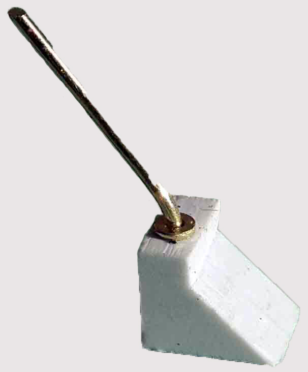
5.33.2 Enlarge the hole in the bottom of the sandbox to take 0.5mm wire. Shape a piece of 0.5mm wire to a ‘J’ configuration terminating just short of the rear wheels, remembering that the shorter diagonal edge is towards the front of the loco. Repeat for the other sandbox. On the prototype there was (a ‘trap’ just below the sandbox. This can be represented by a joint in the wire (refer to photos and drawings.
5.33.3 Mount the sandboxes on the EasiChas frames so that the top is level with the top of the frames and the front edge just covers the half-etched dot on the frames.
5.33.4 Take the left hand brake pipe support bracket [S1] and bend over the half-etched part to 90 degrees. If necessary, curve the bracket so that it fits flat on the frames and over the sandpipe. Repeat for the right hand bracket [S2]. Attach the brackets to the frames and sandpipe by soldering or using cyanoacrylate glue or epoxy resin.
Front sand pipes
5.34 Sand pipes were fitted to the front two sets of wheels
5.34.1 Make a notch in the top of the frame etch to take 0.7mm wire at 20mm from the front edge of the frames both sides.
5.34.2 Take a piece of 0.7mm wire and bend the first 3.5mm over at a right angel with a fairly sharp bend, then shape the rest of the wire to shape around the brake hanger.
5.34.3 Solder in position in the top edge of the frame.
5.34.4 Take a front sandpipe bracket [S3], curve the end round a piece of 0.7mm wire, cut to length and attach to the sandpipe and frames by solder or using cyanoacrylate glue or epoxy resin.
5.34.5 Repeat for the other three sandpipes.