The following additional items are provided in the kit and may be used if the builder requires:
Replacement brake blocks and hangers
Each side is manufactured from four etches and hinged behind the centre crank pin. There are also overlays for the bosses. The left hand side and right hand side rods are the same.
Cut one pair of leading coupling rods from fret [L16 & L17].
Open the crankpin holes using a 1.5 mm drill. When complete drill a hole using the same size drill perpendicular in a scrap piece of wood. Leave the drill in the hole in the wood. Tin the mating surfaces of a pair of coupling rods and place over the drill. This holds one end of the rods accurately ready for soldering. It is critical to align the two halves exactly in order to make one rod so take some time tweaking. See photo

Place a little flux along the top surface of the rod and apply heat; the solder on the soldering iron will run down between the rods and join them. The secret is to apply only a little solder at a time. Solder will fill the “cusp” and give the impression of a solid rod. See photo left. Repeat for the whole length of the rod.
Next cut one pair of trailing coupling rods [L18] and [L19] and assemble in the same way keeping the forked end clear of solder.
Repeat for the other leading and trailing rods.
There are two different boss overlays for the front rods and another two for the rear rods. Working from the front of the locomotive, half-etched boss overlays [L20] are fitted to both the inside and outside of the front coupling rod boss and half-etched large bosses [L21] are fitted to the inside and outside of the front of the centre boss. The half-etched fork overlays [L22] are fitted to the inside and outside of the forked end of the back rod. Finally, half-etched boss overlays [L20] are fitted to the inside and outside of the trailing end boss. Using the appropriate bosses, apply each boss holding it in place with a cocktail stick and solder in place using the same technique as for joining the rods. Clean up each rod with files. Carefully blend the bosses into the front face of the rods.

The rear length of each rod has a knuckle joint to be manufactured. The front and rear rods are joined with a short length of 0.9 mm nickel silver wire pushed through from the front and then cropped back on the rear. leaving about 0.5 mm proud. See photo.
To stop solder flooding the joint apply a little oil to the surfaces not to be soldered - this will prevent the solder running into the joint. Keep the rear of the rod clean. Solder can then be quickly applied with a very hot iron to the back of the rod to fix the wire in place. Clean off excess solder leaving enough to keep a strong joint. See photo above of completed rods.
Repeat for the other rods on the other side of the loco, using the same part numbers.
Open up the crankpin holes so that the crankpin bushes will rotate in the rod. This can be done with a reamer, broach or a fine Swiss file
Fit the rods to the wheels and test run. A comparison between the Bachmann rods (lower) and the replacements is shown in the photo.

Note: it is possible to remove the keep plate if fitting the brake shaft as the bends in the frames and keep plate have been designed to allow this.
The brake shaft can be made up with or without the handbrake lever and the steam brake lever between the frames, and either with the original Bachmann outer brake shaft and brake pull rod levers or replacement ones.
Cut a piece of 0.6 mm wire 22 mm long.
If not fitting the handbrake lever and steam brake lever, cut a piece of 1.2 mm tube to fit between the brake shaft brackets on the frames. Insert between the frames, feed the 0.6 mm wire through one frame, through the tube and through the other frame, soldering all in place with an equal amount of 0.6 mm wire protruding each side.
If fitting the hand brake lever, cut two pieces of 1.2 mm tube 11 mm and 2 mm long.
Starting from the brake shaft bracket on the left hand side looking forwards, put the piece of 0.6 mm wire through the bracket, then slide over the inner end of the wire the spacing washer [L23], then the half-etched washer [L24], then the handbrake lever [L25], then the 11 mm length of 1.2 mm tube, then the steam brake lever [L26]. File the 2mm length of tube to fit between the steam brake lever and the other brake shaft bracket. Finally push the 0.6 mm wire through the short length of tube, and then through the brake shaft bracket on the other side of the frame. Ensure the steam brake lever is the correct way up.

Take the two handbrake pull rods [L27] and [L28] and open out the holes to clear 0.5 mm wire.
Then fold the half-etched top piece of [L27] back on itself on the opposite side to the full etched piece.
Drill a 0.5 mm drill vertically into a piece of scrap wood then first place [L28] over the drill with the full etched piece upwards and then [L27] with the full etched piece downwards, align the two on top of each other and solder together.

With the handbrake lever orientated so that the fold over top section is adjacent to the nearest frame, put an over length piece of 0.6 mm wire through the handbrake pull rods and the hand brake lever, adjust the rod and lever angle as shown in the diagram and attach the handbrake lever to the frame (the top of the lever should be level with the bottom edge of the slots in the frame for the buffer beam brackets and should rest against the edge of the guard iron).
Attach the steam brake lever to the underside of the frame cross piece.
Ensuring that an equal amount of 0.6 mm wire is protruding either side of the frames, solder the wire, tube and levers in place. Solder the wire through the joint in the handbrake lever and trim back both sides.
Open out the holes in the pull rod levers [L29] and pull rod lever spacers [L30] to 0.6 mm.
Drill a 0.6 mm hole vertically in a piece of scrap wood. Insert a piece of 0.6 mm wire and then place over the wire a pull rod lever [L29], a pull rod lever spacer [L30] and another pull rod lever [L29]. Using a piece of 0.6 mm wire in the smaller hole to align the two parts of the lever, solder the pull rod lever together. Repeat for the second lever.

Replacement brake blocks and hangers
The plastic brakes are rather nicely moulded. However metal replacement brake hangers can be fitted if the Bachmann brake hangers are lost or a metal replacement is preferred. Remember plastic does not produce an electrical short and the wheels are sprung, so move vertically!
If fitting the etched replacement brake hangers/blocks, the brake gear needs to be removable otherwise it is impossible to remove the wheels.
Take the brake hangers [L31] and the left hand brake block overlays [L32]. Open up the holes in the top, middle and bottom of the brake hangers, the top to clear 0.5 mm wire, the middle to clear 0.7 mm wire and the bottom to clear 0.6 mm wire.
Solder together the brake hangers [L31] and the left hand brake block overlays [L32], utilising a short piece of 0.7mm wire in the centre hole to assist alignment. Trim the wire to length. Repeat for the right hand brake hangers using parts [L31] and [L33].
Remove the wheels and EasiChas from the Bachmann chassis block. Cut and file off the ‘saddles’ that would have been used to re-fit the plastic Bachmann brakes on the frames and remove the two forward extensions that support the saddles on the front of the keeper plate.
Attach three pieces of 0.5 mm wire to form the support wires across the mainframes using the holes provided protruding and equal amount (at least 5 mm) beyond the frames on both sides. If using the later type of brake hanger bracket, slide the brake hanger bracket inner etches, [L34] for left hand side, [L35] for the right hand side, over the wire and solder to the frames with the vertical longer face leading (see photo).
Cut six short pieces (around 1.0 – 1.5 mm) of 1.0 mm tube. Slide one piece onto either side of the leading support wire


Place a brake hanger/block on each side of the leading wire and position them the correct distance in to suit the wheels you are using. Slide the tube up to the brake hanger/block. Remove the brake hangers and solder the tube to the wire. Repeat for the centre and trailing wheels.
Cut three pieces of 0.6 mm wire 28 mm long to form the brake tie bars.
There are two ways now to attach the brake hanger assemblies to the brake tie bars (not the support wires).
The easiest is to make up a jig from a piece of wood, plastikard etc. the same distance across as the outside measurement of the tube soldered to the support wires as described above.
(We used a piece of wood with the ends squared off, with the brake hangers held in place with blu-tac).
One of each hand of brake block is then attached to each side of the jig with the bottom end protruding beyond the jig.
A length of 0.6 mm wire is then put through the holes in the bottom of the brake block assembly, with an equal amount protruding each side. Solder the wire in place.
Repeat for the other two brake block/tie bar assemblies.
The less easy way is to assemble the brake block/tie bar assemblies in position.
This is done with the wheels in place. If you get flux on the treads of the wheels they will rust – we protect them with a thin piece of masking tape during this process.
With the frames upside down, position the two brake hangers on the leading support wire. Slide a piece of 0.6 mm wire through the bottom hole of both brake hangers.
Holding one of the leading brake hangers vertically resting against the wheel, solder it to the 0.6 mm wire (not to the brake hanger cross wire). Repeat for the other side.
Repeat for the other two brake block/tie bar assemblies.
Check that the brake hangers are in the correct position across the face of the wheels. If not, adjust either the 0.6 mm tie bar or the small piece of tube on the cross wire, or both.
Having made sure that there is a good soldered joint between the cross wire and the frames, with a piercing saw cut the brake hanger wire between the frames. As long as the first cut is made with a saw, the wires can then be trimmed back with cutters. Note – the first cut must not be made with cutters.

Take the two brake pull rods [L36] and [L37] and attach the leading and centre pull rod overlays [L38] to the inside of the pull rod (the inside is the side which has a part half-etched at the rear end.
Attach a rear pull rod inner overlay [L39] to the inside of the pull rods and a rear pull rod outer overlay [L40] to the outside of the pull rods.
Drill out all the holes 0.6 mm.

Place the two brake pull rods over the tie rods on each side of the brake blocks and adjust sideways to give sufficient clearance so as not to touch the wheels when they are at the limit of their sideplay.
Pull the leading tie rod forwards to give sufficient clearance between the brake block and the wheel and solder one of the pull rods to the tie rods.
Repeat for the other side pull rod. If you are still happy with the clearances, solder the pull rods to all the other tie rods.

Measure the distance between the frames and the inside of the pull rods. Cut two pieces of 1.2 mm tube to these lengths less 0.4 mm if no brake shaft bracket overlays are fitted, or less 0.6 mm if they are.
Take the pull rod levers and cut the 0.6 mm wire to half the length of the of the 1.2 mm tube and solder the pull rod levers into the tube. Trim the out wire back flush with the outside of the levers.
Cut back the 0.6 mm wire through the brake shaft to just short of the same length so that the tube and pull rod levers fit over the wire and but up to the face of the brake shaft bracket on the frames.

Using two short pieces of 0.5 mm wire, mount the pull rod ends [L41] in the fork of the pull rod lever so that the half etch part of the pull rod ends are outwards.
Adjust the angle of the pull rod levers to approximately 15 degrees (see photos). Solder the half-etched sections of the pull rod end to the pull rod, then solder the wire through the joint between the pull rod end and the pull rod lever.
Do not solder the tube to the frames.
Repeat for the other side.

The early type brake hanger brackets (outer only) were not included on the main etch. These will be provided on an additional etch.
Finally attach the brake hanger bracket outer etches. For the early type, [E1] for the left hand front and rear, [E2] for the left hand middle, [E3] for the right hand front and rear and [E4] for the right hand middle. For the later type, [L42] for left hand side, [L43] for the right hand side.
Place over the wire on the outside of the brake hangers and solder in place.
Trim back and file the support wire to the outside of the brake hanger.
The brake hangers should just clip off the ends of the cross wires.
The photo shows the position of the later type brake hanger brackets on a similar loco.
On the prototype, behind each side of the buffer beams are large brackets which also support the sandboxes. These are slightly different front and back.
Take the front buffer beam bracket left [L44] and emboss the rivets through the half-etched holes. Take the front buffer beam bracket upright left [L45] and attach to the front buffer beam bracket at right angles with the full etch part towards the front.

Attach the bracket assembly to the slots in the front left side of the frames. And then attach the front angle strip [L46] to the frame above the bracket.
Repeat for the other front buffer beam bracket [L47], upright [L48], and angle strip [L46].
The rear brackets, buffer beam bracket left [L49], buffer beam rear upright [L50], rear angle strip [L51], buffer beam bracket right [L52], buffer beam upright right [L50], are assembled and attached in the same way to the rear of the frames.
Modify the Bachmann sand boxes but do not add the plastic strip to the back. Attach them to the underside of the buffer beam brackets with the circular sandbox filler engaged with the curve in the edge of the bracket using cyanoacrylate glue or epoxy resin.
Refit the Bachmann sand pipes or make new ones from 0.7mm wire.

The splashers fitted to the Bachmann body are over scale to accommodate 00 wheel flanges. If modelling in P4, a set of reduced size splashers is available as a separate etch from Brassmasters.
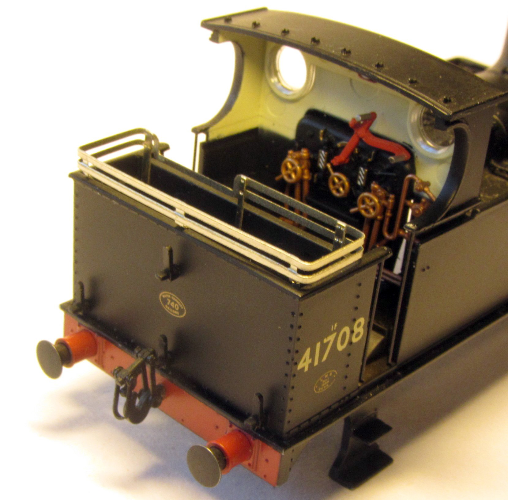
There are three options provided for in the kit, two for the open cab, and one for the closed cab. These are continuous with a dropped section for the hand brake handle or gapped for the open cab, and simple replacements for the closed cab.
Whichever coal rails you are using, bending is made easier using the jig provided.
Take the jig [L53] and file the cusp in the slots in the jig for the coal rail uprights and also the circular corner cut-outs. Mount four pieces of 1.0 mm wire approximately 5 mm long vertically in the corners of the jig. As always, the easiest way to get them vertical is to drill a vertical hole in a piece of scrap wood and insert the wire in this whilst soldering to the jig. There is sufficient wire in the kit to allow for this.


For the open cab version, take the chosen coal rails ([L54] for the dropped section version or [L55] for the gapped version) and push through the rivets using the half-etched holes.
Position the coal rails along the back of the jig and curve the corners around the wire, one corner at a time.
Check that the corner radius is tight and at 90 degrees. We used a 1.0 mm drill to help with this.
For the continuous rails, attach the two ends to each other.
Bend the legs inwards along the rear edge of the coal rail using the half-etched hole as guide.
Place the slot in the jig over the horizontal part of the leg and bend downwards.


For the closed cab version, utilise the open cab gapped rails [L55]. It will be necessary to trim back the rails to a suitable length to attach to the cab sides, or bend round to attach to the cab back.
An additional pair of uprights is provided [L56] and should be added as required to each side of the bunker.
Attach the coal rails to the inside of the Bachmann bunker using cyanoacrylate glue or epoxy resin.